End Table with Kumiko Panels
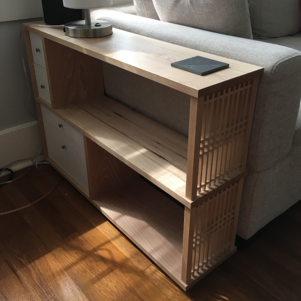
Hickory End Table: dimensions – 35″ wide x 9″ deep x 25″ high, finish – lacquer (white & clear topcoat).
This table is my first original design (that is, I came up with the overall form without consciously working off of any existing design although I’m sure I implicitly borrowed ideas from everywhere) and features the kumiko panels that I showed at February 2019 Meeting.


This article summarizes my design process as well as the construction process of the table.
Design
The project began with an end table that my wife found online. What she liked about this particular table was that it has shelves and one of its ends is open. I, on the other hand, wanted to use the hickory board that I had on my lumber rack. So, I took her desirable features, the width of my hickory board (9″), and the couch dimensions (36″ deep, 25″ high) and started sketching a several designs for the table:
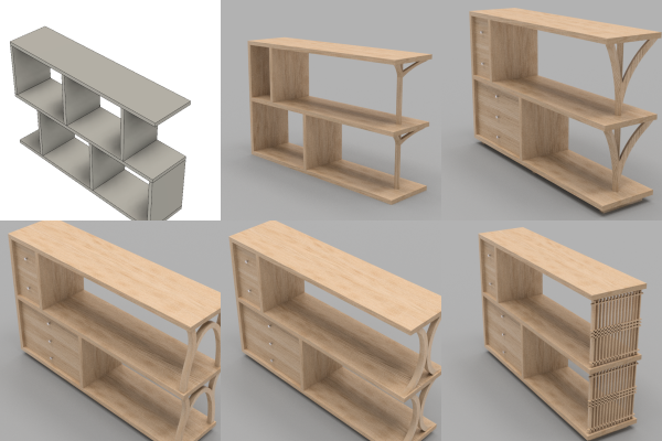
You can see the evolution in the design candidates. We talked about each design and pinpointed what we liked and what we didn’t like. The desirable features were kept in the next iteration while the undesirables were purged. The design of this table took place in December 2018, and you can see the influence of [brwc_user id=”2″]’s the bent lamination table in the bottom left designs. Ultimately, we settled on the kumiko panels for the open end of the table. Here is the rendering of the final design:
There are 2 differences between the kumiko design candidate to the final design: kumiko lattice density and painted drawers. In the initial design, the kumiko vertical members were too dense both aesthetically and structurally. The final design appears sturdier and better balanced with the rest of the table.
The painted drawers came as a last-minute realization that I didn’t have enough hickory for the project (this was after making a trip to a lumber yard to get an additional board). Rather than returning to the yard for more lumber, I opted to use maple off my lumber rack for the drawer fronts and paint it. The painted drawers actually provide a design benefit as the paint lift the (perceptual) weights off of the drawers, making the table aesthetically more balanced.
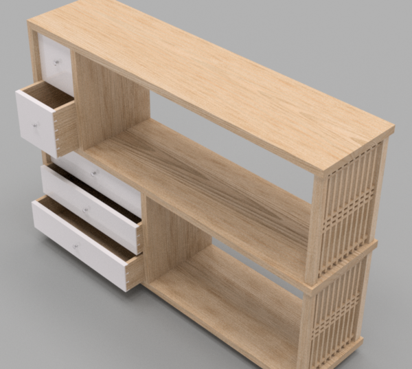
There are two other design features that are worth mentioning here: the continuous grain pattern on the outer structure and the sizing of the drawers.
Similar to the waterfall tables, the outer shell of the table was constructed from one board. Naturally, this called for case miters to join outer boards. For the design continuity, I choose v-groove dado to join the middle shelf to the vertical outer member.
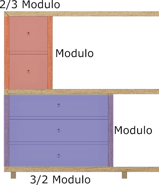
To practice the integer proportion based design approach in Walker & Tolpin’s By Hand & Eye, I laid out the drawers to have 2:3 and 3:2 ratios. I used the shelf height as the modulo (the unit length) and made the bottom shelf drawers to be 3/2 of the modulo while the upper shelf drawers to be 2/3 of the modulo. The use of reciprocal proportions connects the top and bottom sets of drawers. (Looking at the design now, I’m not sure why I set the widths to include the casing as it hides the intended proportions….)
Construction
The project was built in 4 phases:
- Milling & cutting joinery of carcass
- Making kumiko panels & glue up carcass
- Making the drawers
- Making the base, apply finish, & install hardware
Below are the brief descriptions of each phases.
Phase 1. Carcass Milling and Joinery

Milled carcass parts Removing snipes
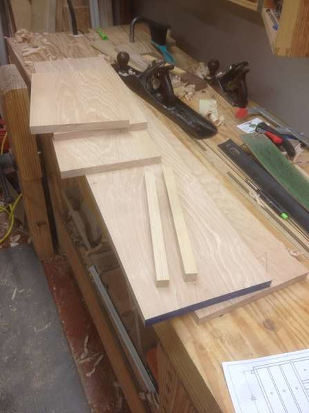
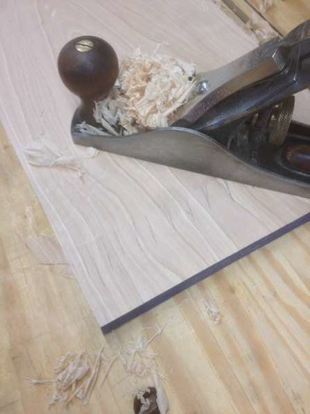
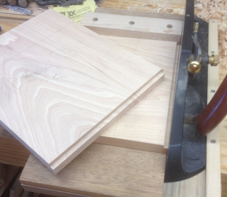
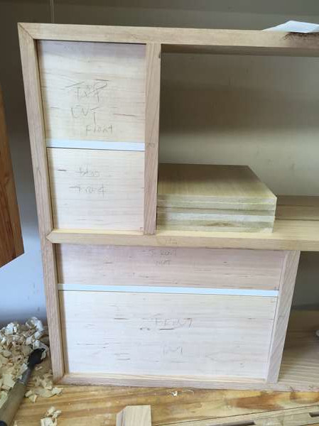
The table carcass is made from (heavy) 3/4″-thick hickory. The boards are first crosscut to rough lengths and ripped to rough widths. (Rough dimensioning of the stock minimizes the jointing effort.) I then skip plane faces with bench planes until the boards sit flat on the workbench. Then, they were passed through the thickness planer down to the final thickness. If I laid out parts to use the sniped ends, the snipes were promptly removed with a hand plane. (I usually don’t plane all the way and spread out the snipe just enough over a couple feet so it cannot be seen by naked eyes.) Then, one edge was jointed by hand followed by ripping to the final width on the table saw. I left the horizontal shelf boards intentionally long until just before the glue-up to avoid any mishaps with end-grains.
As described earlier, the outer corners were joined by case miters without any reinforcements. The middle shelf was joined to the vertical outer panel by “faux v-groove dado joint”. The horizontal panels were left a tad longer then their final dimensions, and they were trimmed right before the glue-up to make sure their lengths are correct and to avoid accidental end-grain tear-offs.
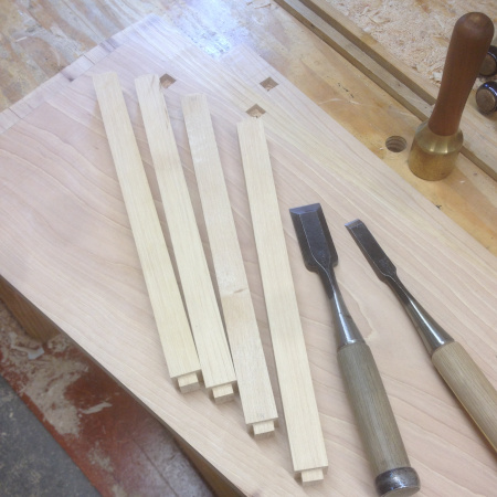
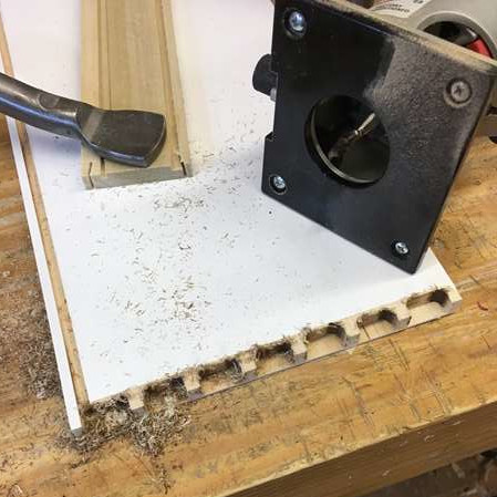
The inner vertical panels are joined to the horizontal panels by stopped dados. The 1/2″-wide dados were routed on the horizontal panels with a 1/2″ spiral bit, and the vertical panels received rabbets such that the thickness is 1/2″:

Mark the length of the panel off the end panel. 
Cut shoulders and trimmed to dado depth
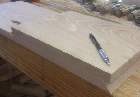
This is a trick that I learned from The Wood Whisperer (Marc Spagnuolo) on YouTube some time ago, and I’ve been practicing regularly ever since. It’s much easier to fine-tune rabbet thickness than dado width. I also like to orient the rabbeted side as the show side of the panel as it hides imperfections of the dado walls.
Also, I did not crosscut these inner vertical panels to the planned length. Instead, the length was taken from the vertical end panel by aligning the rough-lengthed inner panels to the end panel and transferred the length of the inside face, leaving excess stock to both ends. Then I marked the actual crosscut line to the outsides of the transfer marks, offset by the dado depth. In fabrication, I cut the rabbets first (to get the correct length of the exposed section) then trimmed the rabbets to the right width to fit in the dados.
The final carcass parts that I prepped were the columns. These columns were attached to the horizontal panels by square mortise-and-tenons.The mortise locations were marked with knife, then the majority of the waste was hogged out on the drill press, then the mortise walls were chiseled to the knife lines. Tenons were cut with the bandsaw then fine-tuned with chisels and a router plane. After all the joints were cut, I dry-fitted all the carcass parts to check all the dadoes properly lined up:

Column M&Ts 
Dry-fitting carcass parts
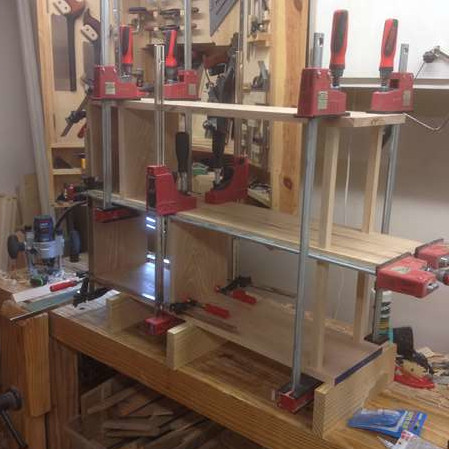
To get to the carcass glue-up, I also needed the kumiko panels and the drawer dividers. I reached this point around the holidays (my table saw also went out of service right before cutting the miters) I ended up putting the project in hiatus for a little over a month, leaving the carcass in the clamps and crossing my fingers that they won’t move much… Unfortunately, the panels cupped a little, which caused a couple challenges later on.
When I returned to the shop, the drawer dividers (7/16″ thick) were fitted to the carcass. They were milled to dimension then notched to fit into the stopped dados on the carcass panels. Once ready, I taped the glue surfaces off and spray painted the edges white.
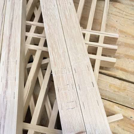
Phase 2. Making Kumiko Panels & Carcass Glue Up
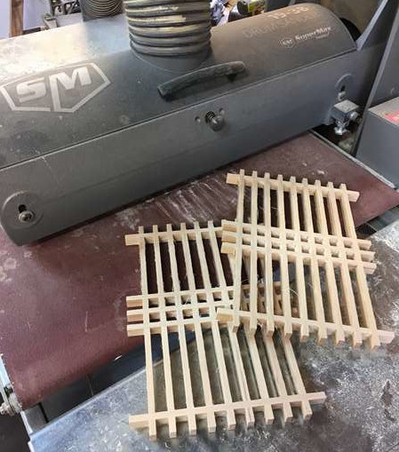
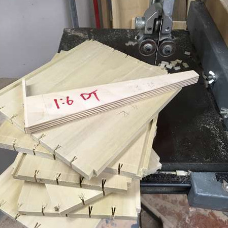
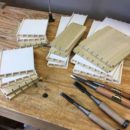
My senbon-goshi kumiko pattern uses the horizontal spacing to be twice the thickness of the kumiko stock, and the vertical spacings are 1:5:1:1:5:1 with respect to the horizontal spacing (if this makes any sense). I refer readers on the kumiko making process to my other post, titled Kumiko Coasters. (While it is for a different pattern, the same procedure could be followed.)
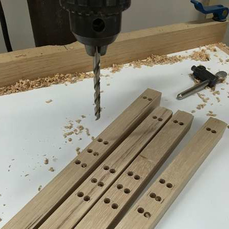
To attach the panel to the columns of the table, I made the horizontal kumiko members 1/4″ longer to both ends so they could be fitted to the mortises on the columns. The mortise locations were marked then mortised using the drill press and chisel:
Mark, Drill, & Chisel; rinse and repeat
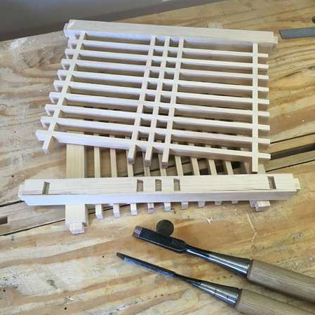
Once these mortises were cut, it was time for the carcass glue-up. I did the carcass glue-up in 3 stages: bottom half, top half, then the end panel. Here are the first two:
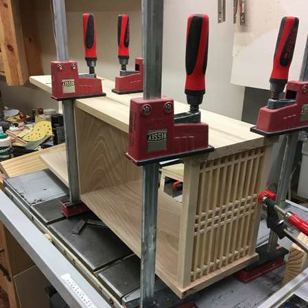
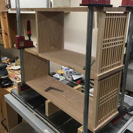
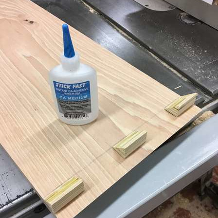
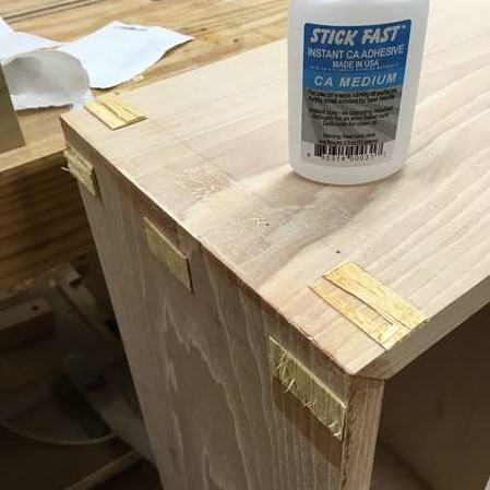
For the end panel glue-up, I first attached glue blocks with CA glue to maximize the clamping pressure on the miters:

Glue blocks Emptied clamp rack Knocked them off w/mallet
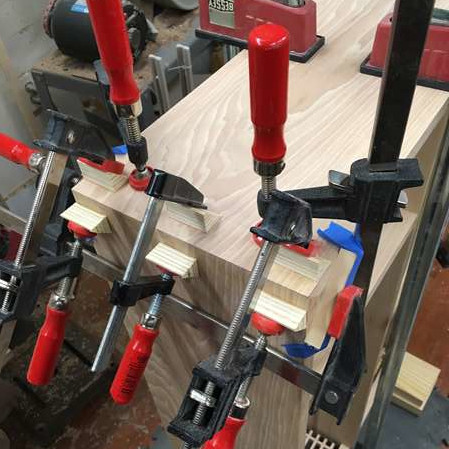
I used PVA glue in the first 2 stages (kumiko panels were left afloat) but chose epoxy for the miters. I used epoxy to mitigate the slight cupping in the panels due to the month-long hiatus from shop. The wood movement took the miters faces out of wack, and they no longer came together tight when butted together. So, I used (1) clamping pressure to force the fit and (2) any gap left to be filled by epoxy. This worked well, but caused another issue later (yep, chain reaction of errors)…
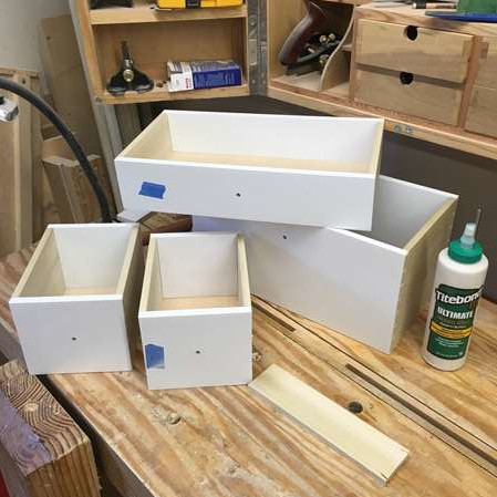
Phase 3. Making Drawers
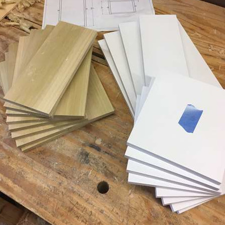
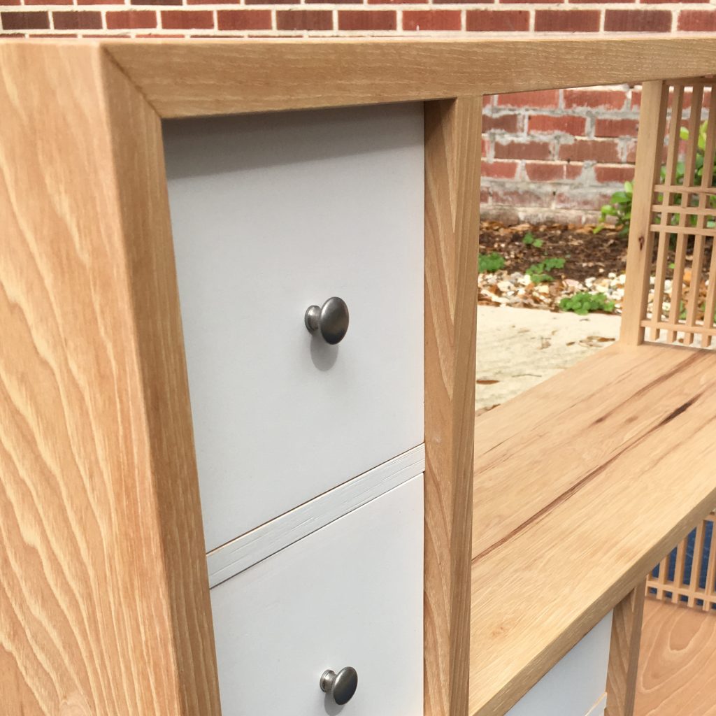
With the carcass glued up, I then turned my attention to the drawers. The fronts are maple, painted white, and the sides are poplar with 3/16″ plywood bottoms. The thickness of the sides are 3/8″ while the fronts are 7/16″. I made a design change for the drawer configuration: reduced the number of drawers on the bottom shelf from 3 to 2. This change accommodates what we want to put in them.
After milling the parts to the rough dimension with the final thicknesses, the drawer fronts are fitted to the openings. This is where the cupping mishap ended up (compounded by the stressful glue-up). Not only the openings were not quite square, the sizes on both ends of the openings were not the same. One feature of this table is that these drawers open to both sides, meaning that drawer fronts must fit through the entire span of the opening. Something that you don’t need to worry about for standard drawers. While I ultimately got them fitted, the fit ended up on a loose end, and the gaps along the four sides did not come out the same.
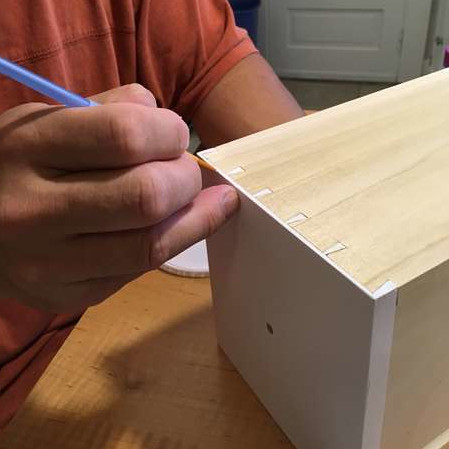
After the drawer fronts were fitted, they were prefinished with white lacquer spray. While the paint was drying, I dimensioned the sides to match the height of the fronts and ran grooves for the drawer bottoms. Then, it was time to tackle the semi-blind dovetails. Much like the rest of the project, I approached it with mixed tooling:
All the parts Started tails with bandsaw Routed out pin-board waste with router Fitted with chisels
The tails were cut first with bandsaw. I used a shop-made jig (well, a plywood wedge with a stop) to cut consistent angle. The waste was then chiseled out then pared to the baseline. The waste between the pins was first hogged out with the trim router (with 1/8″ spiral bit) free-handed, then chiseled to the lines.
After bottoms were cut to fit, the drawers were glued up. After glue cured, the joints were cleaned up with a plane. This, of course, wouldn’t go without planing off the paint, so I had to do an extensive touch-up job.
Phase 4. Base, Finishing, and Hardware
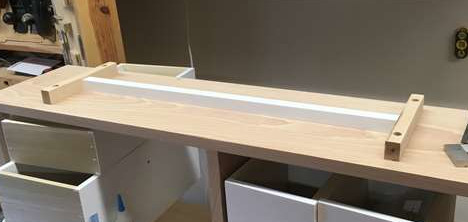
The final assembly to build was the base (1″ tall). In the original design, I planned to have 3 sticks of wood across the bottom panel. But, I ended up using an “H”-shaped base. The crossbar is slightly shorter than the feet, and it is joined to the feet with half-laps. Because I had a little bit of white lacquer left, I painted it although no one will ever see it. The base was screwed to the bottom shelf with oversized through holes.
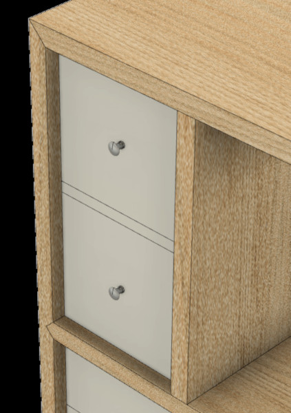
The table was finished with clear semi-gloss lacquer (used 3 rattle cans). After it dried, I applied and buffed paste wax. The final step was to install the drawer pulls. I used Lee Valley’s stainless steel small turned knobs (5/8″Dia x 7/16″High, p/n: 05H22.26). They are well-made pieces that I could friction fit into the mounting holes.
Lesson Learned: Schedule your build properly to minimize the impact of wood movement. Specifically, any assembly with case miters should be glued immediately after the miters are cut.
[simple-author-box]Self-taught hobbyist woodworker, aspired to build fine furniture. As his 15'x8' shop limits housing large power tools, he often takes hand tools to the work to achieve many of his woodworking tasks. Despite being Japanese, he reaches out to western saws and planes first.
Wow! Kesh,great looking side table. I appreciate the detailed article and great photos. They demonstrated the careful attention to details in all phases of the project. I wish my projects came out as well as yours. Waiting to see your next one.